

Interlighting is the practice of placing light sources inside the plant canopy instead of above it. In a high-wire tomato or cucumber crop, the upper leaves intercept most of the light that arrives from a canopy-top fixture, so the lower and middle fruiting layers operate at a fraction of the canopy-top intensity. A linear interlighting module attacks that gradient directly: it emits sideways from a slim bar that hangs between two plant rows, so photons enter the canopy at the height where leaves are actually producing.
This article is a specification walkthrough of the 1206 mm RX-TP6350 interlighting module: its optical geometry, how its PPFD changes with distance, how its three SKUs map to crop stages, and what the official data table states about thermal rise, rated life and electrical interface. It is a distance-and-hardware analysis. It does not compare spectral recipes, and it is not a guide to selecting a canopy-top fixture.
What “Interlighting” Means in a Between-Plant Mounting Position
Interlighting is a mounting strategy, not a fixture type. The distinction matters because every downstream specification — beam angle, bar length, distance band, ingress protection — follows from the fact that the bar is surrounded by foliage on both sides.
Three practical consequences follow from that geometry.
- Emission direction is sideways, not downward. A between-plant bar radiates into the vertical plane of the canopy, so the useful metric is not “intensity at the canopy top” but “intensity at the working distance from the bar”.
- The working distance is short. Between-plant bars are specified over a 0.2 m to 1 m band, and the delivered photon flux density changes steeply across that band.
- The bar lives in a humid, dusty, high-contact zone. Because it sits inside the canopy and close to irrigation lines, enclosure rating and surface temperature rise become selection criteria rather than footnotes, alongside the usual electrical ones.
For background on how supplemental lighting is specified for greenhouse crops — including the daily light integral (DLI) concept that sets a target for the whole 24-hour day — see the Michigan State University Extension overview of choosing a supplemental lighting system. For the general physics and rating conventions of LED light sources (efficacy, lumen maintenance and condition-dependent life ratings), the U.S. Department of Energy’s LED Basics page is a neutral reference.
The Optics of a 1206 mm Linear Interlighting Module
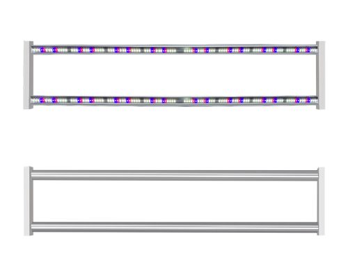
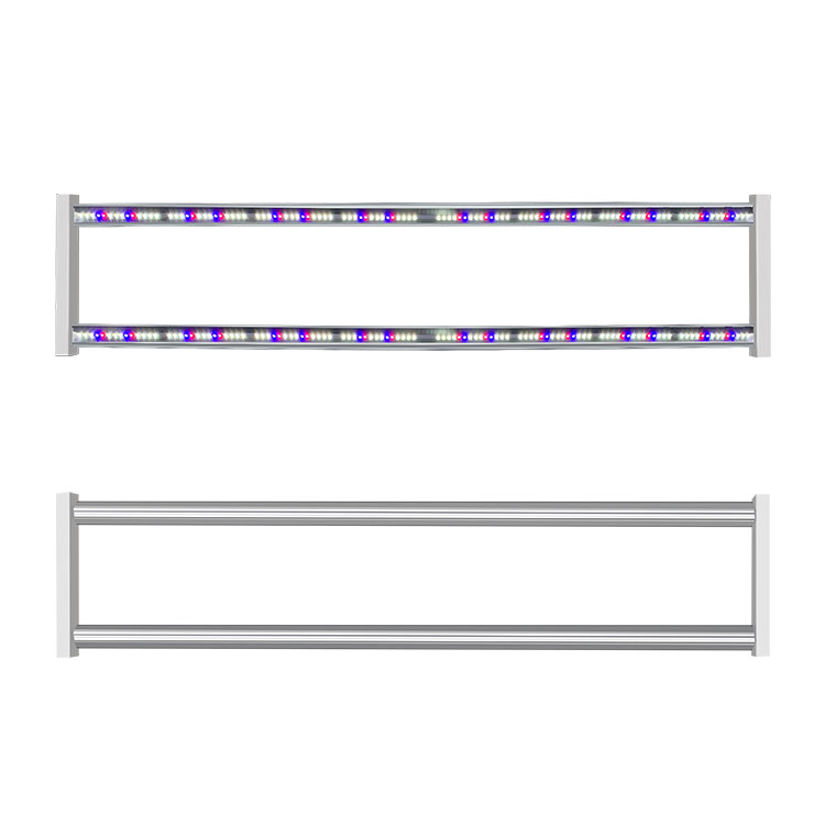
The RX-TP6350 is a linear module measuring 1206 × 63 × 50 mm with 168 LEDs and a 120° emission angle. The 1206 mm length is deliberate: in a high-wire crop, rows are spaced so that a bar can be suspended along the row axis and still deliver a substantially even front along its length rather than a local hotspot and rapid fall-off.
Sideways-facing LEDs behind an ultra-white tempered glass cover produce the between-plant beam. A glass cover is a functional choice for this position: it protects the emitters from spray, condensation and physical contact while keeping the optical path clean, and it is part of the reason the module carries an IP65 rating.

The official product page recommends a mounting band of 0.2 m to 1 m from the module to the target canopy layer. That band, not a single “recommended height”, is the operative specification, because the three SKUs are intended to serve different points on the crop timeline.
PPFD Falls by Roughly Two-Thirds Between 0.2 m and 0.5 m
Photon flux density at a given point is a function of distance, so an interlighting module’s headline number is meaningless without the distance attached to it. The official data table for the RX-TP6350 lists vertical PPFD at three distances, and the falloff is steep.
| Distance from module | RX-TP6350-F1 | RX-TP6350-F2 | RX-TP6350-6K2R4B1 |
|---|---|---|---|
| 0.2 m | 277 µmol·m⁻²·s⁻¹ (18,041 lx) | 265 µmol·m⁻²·s⁻¹ (17,558 lx) | 233 µmol·m⁻²·s⁻¹ (7,694 lx) |
| 0.3 m | 177 µmol·m⁻²·s⁻¹ (11,521 lx) | 174 µmol·m⁻²·s⁻¹ (11,533 lx) | 154 µmol·m⁻²·s⁻¹ (5,099 lx) |
| 0.5 m | 97 µmol·m⁻²·s⁻¹ (6,325 lx) | 95 µmol·m⁻²·s⁻¹ (6,372 lx) | 85 µmol·m⁻²·s⁻¹ (2,825 lx) |
Measured relative falloff from 0.2 m to 0.5 m is therefore roughly −65 % for -F1 (277 → 97 µmol·m⁻²·s⁻¹), −64 % for -F2 and −64 % for -6K2R4B1. Going from 0.2 m to 0.3 m alone loses about 36 % of the delivered density in the -F1 configuration.
These figures are published under specific conditions and must be read with them: the official table states Power Input 230 V AC, an ambient condition of Ta < 25 °C, an optical and electrical tolerance of ±10 %, and the disclaimer that “the above data is for reference only”. The full table is published as the official RX-TP6350 specification sheet.
The practical reading is simple: a mounting plan that differs by 0.1 m from the assumption behind a calculation can move the delivered density by a third of its value. Distance belongs in the mounting drawing, not in a footnote.
Three SKUs Share One Enclosure but Not One Photon Budget
All three RX-TP6350 variants use the same 1206 × 63 × 50 mm body and the same 168 LED count, so the difference between them is not visible in a photograph. The official data table separates them by photon and power budget instead.
| Specification | RX-TP6350-F1 | RX-TP6350-F2 | RX-TP6350-6K2R4B1 |
|---|---|---|---|
| LED count | 168 | 168 | 168 |
| PPF | 148 µmol/s | 143 µmol/s | 125 µmol/s |
| Input power | 68 W | 68 W | 60 W |
| Efficacy (official) | 2.2 µmol/J | 2.1 µmol/J | 2.1 µmol/J |
| Total luminous flux | 9,474 lm | 9,301 lm | 4,020 lm |
| PAR output | 32,103 mW | 30,004 mW | 25,877 mW |
| PPFD @ 0.2 / 0.3 / 0.5 m | 277 / 177 / 97 µmol·m⁻²·s⁻¹ | 265 / 174 / 95 µmol·m⁻²·s⁻¹ | 233 / 154 / 85 µmol·m⁻²·s⁻¹ |
| Official design intent (data table comment) | Seeding, seedling growth | Growth | Red-blue ratio equivalent to 4:1 |
Two facts follow from the table and are worth stating plainly, because they are often assumed away. First, the three SKUs are not a single fixture at three power settings: -F1 and -F2 draw the same 68 W yet differ in PPF (148 vs 143 µmol/s), efficacy (2.2 vs 2.1 µmol/J) and luminous flux (9,474 vs 9,301 lm). Second, the low-power variant is not a dimmed version of the others either — -6K2R4B1 delivers 4,020 lm at 60 W, roughly 42 % of the -F1 luminous flux.
Stage matching in this article is driven by delivered density at the working distance and the official design intent label, not by spectral recipe selection. That is the deliberate scope of this analysis: the selection question here is “how far from the canopy, on which tier of the crop timeline, and at which distance”, and the answer set is the official table above.
Extending the Curve to the 1 m End of the Mounting Band
The officially measured points stop at 0.5 m, but the officially permitted mounting band extends to 1 m. Because the falloff is monotonic and steep, the 0.2 m figure cannot be reused as a design assumption for a 1 m installation.
| Distance | Relative density (official points, -F1) | Reader calculation of the -F1 trend beyond the measured range |
|---|---|---|
| 0.2 m | 277 µmol·m⁻²·s⁻¹ (100 %) | officially measured |
| 0.3 m | 177 µmol·m⁻²·s⁻¹ (64 %) | officially measured |
| 0.5 m | 97 µmol·m⁻²·s⁻¹ (35 %) | officially measured |
| 1.0 m | not published | project-specific; must be calculated or measured |
The last row is intentionally blank. Extrapolating a fixture’s inverse-square behavior beyond the published measurement points is reader-side arithmetic, not an official rating, and the correct engineering response is to measure on site or to mount at a shorter distance and use the measured band. Treat any 1 m number quoted without a measurement as unverified.
Thermal Rise and Rated Life in a Sealed Between-Plant Module
Because an interlighting bar sits inside a canopy where airflow is obstructed by foliage and irrigation hardware, its thermal specification deserves the same attention as its optical one. The official table gives three numbers that should be read together.
- Surface temperature rise Tc: 18 K. This is a rise above ambient, so the absolute surface temperature depends on the ambient condition of the installation.
- Rated life: 25,000 hrs, with the stated condition Ta < 25 °C. The condition is part of the rating, not a suggestion; a hot house that holds ambient above 25 °C cannot assume the same number.
- Operating temperature: −30 °C to 40 °C. This is the envelope in which the module is specified to run, and it brackets both cold unheated structures and warm summer houses.
Official optical and electrical values carry a ±10 % tolerance and the published note that data is for reference only. It is worth keeping in mind that LED life specifications are always condition-dependent — rated life is a projection from a test condition, not a promise of calendar years — which is exactly why the Ta < 25 °C qualifier accompanies the 25,000 hr figure. The U.S. Department of Energy's LED Basics page describes how LED lumen maintenance and life ratings are derived and why conditions matter.
Mounting, Ingress Protection and Electrical Interface
Installation in the between-plant position involves repeated hardware work inside a trellis, so tooling and mounting design are part of the specification.
- Rear mounting bolts, tool-free, with cascading fixation. Bars are fixed and chained from the rear face, which keeps the front optical face clear during installation and service.
- IP65 ingress protection. Dust-tight and protected against water jets, which suits a position near misting and irrigation lines.
- Ultra-white tempered glass cover. The optical window is glass rather than a polymer lens, protecting 168 emitters from contact and condensation.
- AC 100–277 V input, power factor > 0.9. The wide input range lets the module run on common single-phase mains voltages without a separate low-voltage driver stage in the mounting assembly.
- Compliance: CE, RoHS, FCC.
Specification-Dimension Comparison: Between-Plant Module vs Canopy-Top Fixture
The two mounting positions answer different questions, and a like-for-like comparison across the dimensions that actually drive a design decision is more useful than comparing headline numbers.
| Specification dimension | Between-plant linear module (1206 mm class, as in RX-TP6350) | Canopy-top fixture (general reference) |
|---|---|---|
| Mounting plane | Inside the canopy, between plant rows | Above the canopy, on truss or rail |
| Emission direction | Sideways, 120° beam into the vertical canopy plane | Downward onto the canopy top |
| Specified distance | 0.2–1 m from the bar to the target layer | Typically 0.3–1.5 m to canopy top, crop dependent |
| Characteristic intensity change | Steep within the working band: about −65 % from 0.2 m to 0.5 m | Depends on beam distribution across the whole canopy footprint |
| Thermal environment | Obstructed airflow inside foliage; surface rise specified as Tc 18 K | Open airflow above the canopy |
| Ingress and protection emphasis | High — spray and contact zone; IP65 glass-covered | Medium — protected by height |
| Life rating basis | 25,000 hrs at Ta < 25 °C (official condition) | Varies by product family and test condition |
| Electrical input | AC 100–277 V, PF > 0.9 | Varies by family; often dedicated driver stage |
| Primary design question | Which distance, which crop stage, how many bars per row | Which intensity at the canopy top, DLI coverage |
Neither column is “better”. A between-plant module is chosen when the limiting factor is light reaching the lower and middle fruiting layers; a canopy-top fixture is chosen when the limiting factor is total daily light over the whole canopy. Judging an interlighting bar by a canopy-top metric, or the reverse, produces the wrong answer in both directions.
Application Guidance: Where the RX-TP6350 Fits
The following guidance applies the official specifications to specific situations. It is confined to this section and to the FAQ below; every other section above is specification and method.
- High-wire tomato and cucumber rows with a dense upper canopy. The between-plant position targets the vertical layers that a canopy-top installation under-serves. This is the application named on the official product page.
- Crop-stage planning with the same hardware family. Where a site wants a light budget to change over the crop timeline, the official data supports a three-way split: -F1 is labelled for seeding and seedling growth, -F2 for growth, and -6K2R4B1 for a red-blue equivalence specification — with the note that delivered density also differs by 15 % or more between -F2 and -6K2R4B1 at 0.2 m.
- Installations with limited distance tolerance. Where bars must hang at 0.2–0.3 m from the target layer, the published falloff shows this band is the highest-density operating region; where bars must be far, the design should rely on measured rather than extrapolated numbers.
- Warm houses with airflow restrictions. Because the life rating is conditioned on Ta < 25 °C and the surface rise is 18 K, ambient management inside the canopy band is a first-order design input, not an afterthought.
- Wide-input-voltage sites. AC 100–277 V input and PF > 0.9 simplify electrical planning across single-phase supplies.
The module is unlikely to be the right answer where the entire light requirement of a crop is being met from a single canopy-top plane, or where the site cannot maintain the ambient condition attached to the life rating.
FAQ
What is the recommended mounting distance for the RX-TP6350?
The official recommendation is a 0.2 m to 1 m distance between the module and the target canopy layer. Because delivered density changes steeply across that band — about −65 % between 0.2 m and 0.5 m for the -F1 variant — the distance should be fixed in the mounting drawing and used with the corresponding published figure rather than the headline number.
How many LEDs does each RX-TP6350 module use?
Each module uses 168 LEDs in a 1206 × 63 × 50 mm body with a 120° emission angle. The LED count is identical across the -F1, -F2 and -6K2R4B1 variants.
Is the RX-TP6350 the same product as the RX-GW6350?
Yes — RX-TP6350 is the model designation used on the official specification sheet and PDF, and it is the designation used in this article. “RX-GW6350” appears as a legacy alias in one line of older product-page copy; the official data table and datasheet both use RX-TP6350.
How long is the RX-TP6350 rated to operate, and under what condition?
The official rated life is 25,000 hrs at an ambient condition of Ta < 25 °C, with a specified surface temperature rise of Tc 18 K and an operating range of −30 °C to 40 °C. The ambient qualifier is part of the rating and should be reflected in the greenhouse’s thermal design.
Does the RX-TP6350 replace a canopy-top fixture in a high-wire tomato crop?
No. It supplements from inside the canopy. A canopy-top fixture addresses total daily light delivered to the canopy surface; a between-plant module addresses vertical light distribution within the row. The official parameter set for this model is published at 230 V AC and 0.2–0.5 m, which are the conditions to use when budgeting its contribution alongside any existing overhead lighting.
Official evidence and external references
- Official product page: RX-TP6350 interlighting grow light (HTTP 200)
- Official datasheet PDF: RX-TP6350.pdf (HTTP 200)
- U.S. Department of Energy, LED Basics (HTTP 200)
- Michigan State University Extension, How do I choose a supplemental lighting system for my greenhouse? (HTTP 200)
- DesignLights Consortium, Horticultural Lighting (HTTP 200)
Koray is a lighting manufacturer with 17 years experience in LED horticultural and commercial luminaires and 300+ patents across its product portfolio.




Leave A Comment