
The Difference Between a Dimmer, a Driver and a Control Interface
A dimming interface is the electrical boundary at which an external signal tells a power supply how much current to deliver to its emitters. It is not the power supply itself, and it is not the luminaire. Three separate parts therefore decide what a room can actually do: the driver, which converts mains power into the current the LED array needs; the interface, which receives a control signal and passes it to that driver; and the emitter array, which sets the spectrum. Confusing the three is the most common reason a dimming upgrade turns out to be more expensive than expected.
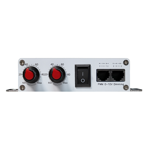
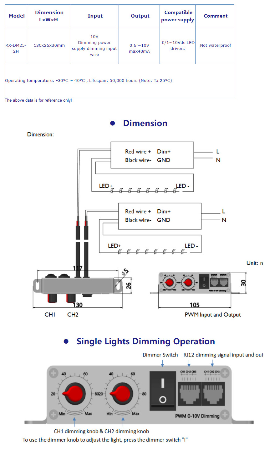
A control interface product exists because most dimmable drivers already accept an external signal but ship without a way to generate it. A 1-10V dimming interface is a low-voltage control device that outputs a dimming signal into a driver that accepts analog control. In the case of the Koray DM25-2H, the official product page describes a dual-channel tunable-spectrum dimmer with a DC 1-10V input, a 40 mA output, RJ11/RJ12 telephone-line wiring and support for dimming in parallel, and it states that the unit requires no additional power supply of its own. The official page does not list which light engine the interface must be paired with, because the compatibility statement is written the other way round: the unit works with 0/1-10V-interface dimmable electronic LED drivers and power supplies generally, with an example given of a three-in-one dimmable driver of the type commonly used in horticultural luminaires. That framing is what makes an interface product portable across a fixture fleet rather than tied to one luminaire model.
What “1-10V” Means in an Analog Dimming Interface
1-10V dimming is an analog control method: a DC voltage between roughly 1 V and 10 V is applied to a dedicated control input, and the driver scales its output current according to that voltage. It is a different scheme from mains phase-cut dimming, which interrupts the AC waveform, and different again from digital bus protocols in which a coded message rather than a voltage level carries the instruction. ACEEE, the American Council for an Energy-Efficient Economy, published a 2024 Summer Study paper titled “Digitization, Standards and Interoperability: Lighting as a System” that describes 0-10V as the most common analog dimming form in North America and situates it among standards such as IEC 60929 and ANSI/ESTA E1.3 (ACEEE Summer Study proceedings). The same analog-versus-digital split is set out from the standards side by the DALI Alliance, whose IEC 62386 overview page contrasts a voltage-level analog interface with an addressable digital bus (DALI Alliance overview).
The practical consequences of the analog route are predictable once the topology is clear. Because the instruction is a voltage level rather than an addressed packet, every driver that receives the same level responds identically, so a group of fixtures on one signal line moves together without any addressing step. Because the control line is separate from mains power, the conductors can be light-gauge and the run can be long. And because the interface is a passive signal source rather than a lighting load, the electrical rating a planner needs to check is the output current it can supply, not a wattage. The official DM25-2H output rating is 40 mA, which is the figure that governs how many driver control inputs one interface can hold in a parallel arrangement; the official page does not state a maximum number of parallel units, so that ceiling has to be confirmed against the drivers actually installed rather than assumed. A 1-10V dimming interface is therefore best understood as a small, current-limited signal device that fans a single instruction out across a powered driver group.
Why Parallel Wiring Changes How a Room Is Planned
The conventional way to dim a multi-fixture room fixture-by-fixture is one control device per luminaire. That approach works, but it multiplies three things at once: the count of control devices, the count of cable runs back to each device, and the number of adjustment points a grower has to visit to change light output. Parallel dimming collapses those three into one. The official DM25-2H product page lists RJ11/RJ12 telephone line for wiring and states that dimming can run in parallel, and it also states that no additional power supply is required for the interface. A telephone-line jack is a terminated, keyed, field-serviceable connector, which is why it is used here instead of an open terminal block: multiple units and driver control inputs can be chained on the same run without hand-terminating each leg.
The planning question that follows is not about brightness but about grouping. Fixtures that share a canopy height, a crop stage and a daily light integral target belong on one signal line; fixtures that do not should be separated, because a parallel line cannot be split by fixture once it is wired. In a sealed flowering room, a propagation shelf and a mother-plant area, that usually means three groups rather than one. The value of a 1-10V parallel interface is that adding the second and third group costs a run of telephone cable rather than another set of controllers, and that a stage change is executed at one point instead of at every luminaire. Grouping decisions made before the cable is pulled are the whole design; after the fact, re-grouping means re-wiring.
Planning Channels by Growth Stage Rather Than by Fixture
A tunable-spectrum fixture separates its emitters into independently controlled channels, and the channel count sets how many spectral mixes the fixture can produce. The DM25-2H is the dual-channel member of a three-model family: the official pages describe a single-channel DM25 measuring 130 × 23 × 30 mm, the dual-channel DM25-2H at 130 × 26 × 30 mm, and a three-channel DM25-3H at the same 130 × 26 × 30 mm panel size. Upgrading channel count therefore stays inside one panel format instead of forcing a different enclosure, cut-out or mounting bracket.
Channel planning is a stage-mapping exercise. A two-channel interface can move a mix along one axis — for example a vegetative-leaning blend towards a generative-leaning blend — while a single-channel interface can only scale total output up and down. The official DM25-2H page does not define which wavelengths sit on which channel, does not publish a dimming curve, and does not state a minimum dimming percentage. Those three omissions are real planning constraints, not marketing gaps: without a published curve, the shape of the low end has to be measured on the installed driver; without channel definitions, the mix at each dial position has to be confirmed against the channel layout of the paired fixture. A planner who needs a documented wavelength-per-channel map should request it from the manufacturer before specifying, and should not infer it from another model in the same family. What the official page does support is the control architecture: DC 1-10V input, 40 mA output, RJ11/RJ12 parallel wiring, operation between 20% and 90% relative humidity, 50,000 hours rated life, and CE, RoHS and FCC marks.
Official DM25-2H Values and the Conditions Behind Them
The table below reproduces only what the official product page states, with the condition or the exact wording attached to each figure. Rows that the official page does not cover are listed in a separate block and are not estimated, and no value is carried over from the single-channel DM25 or the three-channel DM25-3H.
| Parameter | Official value | Condition / official wording |
|---|---|---|
| Product category | Dual-channel tunable-spectrum 1-10V dimming controller | Control interface, no light source of its own |
| Input | DC 1-10V | Analog control level |
| Output current | 40 mA | Signal output to the driver control input |
| Compatibility | 0/1-10V-interface dimmable electronic LED drivers and power supplies | Official example: three-in-one dimmable power supply |
| Additional power supply | Not required | Official wording: no extra power supply needed |
| Wiring | RJ11 / RJ12 telephone line | Official wording: supports dimming in parallel |
| Channels | 2 (dual channel) | Family: DM25 single channel 130 x 23 x 30 mm; DM25-3H three channel 130 x 26 x 30 mm |
| Operating humidity | 20%-90% RH | Official range |
| Dimensions | 130 x 26 x 30 mm | DM25-2H enclosure |
| Rated life | 50,000 hours | Official rating |
| Certifications | CE / RoHS / FCC | Official marks |
| Dimming curve and minimum dimming level | Official product page does not list | Not inferred from other models |
| Channel wavelength definitions | Official product page does not list | Confirm against the paired fixture |
| Ingress protection, operating temperature, maximum parallel units, protocol version | Official product page does not list | Reported as gaps, not estimated |
Control Architecture Compared: One 1-10V Interface Group vs Per-Fixture Adjustment
The comparison below sets the official DM25-2H values against the alternative of adjusting each luminaire on its own. Every DM25-2H cell is an official figure; the second column describes the alternative architecture at the level of what it requires, without quoting any third-party product figure.
Where a Dual-Channel 1-10V Interface Fits: Deployment Scenarios
A 1-10V interface earns its place where fixtures already accept an external control signal and the owner wants spectral or output control without replacing luminaires. A sealed indoor room running a vegetative-to-generative cycle across several luminaires is the clearest case: the drivers are dimmable, the fixtures are dimmable, and the missing part is the signal. A propagation rack and a flowering room on the same site is a second case, because the two zones need different set-points and can be separated onto two parallel lines. A research or trial room is a third, since a controller that can be swapped or upgraded independently of the light engine lets a protocol be re-planned without touching the fixtures; the DesignLights Consortium horticultural lighting programme, which sets quality and control expectations for controlled-environment agriculture luminaires, reflects the same principle — controllable output is treated as part of the luminaire qualification, not as an aftermarket extra.
The interface is the wrong purchase in one situation: when the installed luminaires only accept mains switching or an internal dimmer with no external control input. The official compatibility statement covers 0/1-10V-interface dimmable drivers and power supplies, and nothing else, so a fixture without that input cannot be controlled by this device no matter how the wiring is arranged. Checking that single point before ordering is the whole feasibility test.
| Planning dimension | DM25-2H 1-10V interface on an existing driver group (official values) | Per-fixture adjustment with no external 1-10V input |
|---|---|---|
| Control signal input | DC 1-10V (official) | No external signal input available |
| Signal output | 40 mA (official) | Not applicable |
| Wiring medium | RJ11 / RJ12 telephone line, dimming in parallel (official) | Adjustment carried out locally at each luminaire |
| Additional power supply for the control device | Not required (official wording) | Not applicable |
| Channels | 2 (dual channel tunable spectrum) | One output level per fixture |
| Enclosure | 130 x 26 x 30 mm (official) | Set by the luminaire housing |
| Operating humidity | 20%-90% RH (official) | Not applicable |
| Rated life | 50,000 hours (official) | Not applicable |
| Certifications | CE / RoHS / FCC (official) | Fixture dependent |
| Grouping of fixtures | Every driver on one parallel line follows the same set-point | Each luminaire holds its own set-point |
| Effort at a stage change | One adjustment point per parallel group | One adjustment per luminaire |
| Dimming curve, minimum dimming level, channel wavelength map, IP rating, maximum parallel units | Official product page does not list | Not applicable |
Conclusion
A dimming architecture is chosen on three numbers and one topology. The numbers are the control level the driver expects, the current the interface can source, and the enclosure the control point must fit into; the topology is serial or parallel. On the DM25-2H the official values are DC 1-10V input, 40 mA output, a 130 × 26 × 30 mm enclosure, 20%-90% RH operating humidity, 50,000 hours rated life and CE, RoHS and FCC marks, with RJ11/RJ12 telephone-line wiring and parallel dimming and no additional power supply required. What the official page does not publish — the dimming curve, the minimum dimming level, the channel wavelength map, the IP rating and the maximum number of parallel units — should be treated as open items to confirm against the paired drivers rather than as values to assume. Get those confirmations before the cable is pulled, and a 1-10V control layer can be added to an existing indoor fixture fleet without replacing it.
FAQ
Is the DM25-2H a grow light or a control device?
It is a control device. The official product page describes it as a dual-channel tunable-spectrum 1-10V dimming controller with no light source: it takes a DC 1-10V input and delivers a 40 mA signal into compatible dimmable drivers and power supplies.
What does “no additional power supply required” mean on the official page?
The official product page states that the interface needs no extra power supply of its own, so it is wired into the existing 0/1-10V dimmable driver arrangement rather than being fed by a separate power unit. The same page lists DC 1-10V as the input.
Can several fixtures be dimmed together with one DM25-2H?
The official page lists RJ11/RJ12 telephone line for wiring and states that dimming can run in parallel, which is the arrangement that lets one signal serve a group. The maximum number of parallel units is not published, so the ceiling must be confirmed against the 40 mA output and the control input current of the drivers installed.
Does the official page list the dimming curve or the minimum dimming percentage?
No. The official product page does not list a dimming curve or a minimum dimming percentage, and it also does not define which wavelengths sit on each channel. Those three items are reported here as gaps and are not estimated from the single-channel DM25 or the three-channel DM25-3H.
What are the rated life, dimensions and certifications of the DM25-2H?
The official product page lists 50,000 hours rated life, a 130 × 26 × 30 mm enclosure, an operating humidity range of 20%-90% RH, and CE, RoHS and FCC marks. The IP rating is not listed on the official page.
Why Choose Koray
The DM25-2H is manufactured by Zhongshan Koray Opto-Electronic Co., Ltd., which brings 17 years of experience in LED grow-light manufacturing and 300+ domestic and foreign patents to its control and luminaire ranges.




Leave A Comment