

A grow room has three layers: the light source, the climate, and the layer that decides when each one runs. This article is about the third layer — the wiring and control logic of a bus-based horticultural controller — not about lamp photometrics.
In a controlled-environment facility, photons and climate are two separate loops. Lights produce the daily light integral; ventilation, heating and dehumidification produce the temperature and humidity band. Something has to sit between them, read the environment, and turn the plan into timed electrical output. That device is the control layer, and it is normally specified in a different way from a luminaire: not by micromoles per second, but by channel count, signal protocol, sensor inputs, alarm contacts and schedule depth. This article walks through those five engineering quantities on the KR-GS8P, a 5 W controller built around the Horti-Guru mobile app, and explains what each one changes in a real installation. Optical ratings are deliberately excluded, because a controller has none.
Why Light and Climate Need a Control Layer Between Them
A controller is the device that converts a cultivation plan into timed electrical signals. A sensor bus is a shared two-wire network on which several measurement devices report to one master. A light recipe is a schedule that assigns a spectrum and an intensity level to each growth stage over time.
Those three definitions explain why the control layer exists. Light intensity and photoperiod are not independent variables: the same daily light integral (DLI) can be delivered by a high PPFD over a short photoperiod or a lower PPFD over a long one, and the choice changes electricity use, leaf temperature and climate load. Michigan State University Extension’s Light Management in Controlled Environments resource sets out this intensity × hours logic and the PPFD/DLI conversions that follow from it [1]. Once a grower accepts that light is a dose rather than a fixture rating, the controller becomes the tool that administers the dose — and the dose has to be tracked against temperature and humidity, because both interact with transpiration.
What RS485 Modbus Means for Sensor Inputs
RS485 Modbus (formalised as ANSI/TIA/EIA-485) is a differential serial bus in which two signal conductors carry the inverse of each other, so common-mode electrical noise cancels at the receiver. A differential bus is what allows several instruments to share one cable run through a room full of switching power supplies and fans, at distances that a single-ended signal cannot cover.
The KR-GS8P uses that bus for two measurement classes rather than one:
- Light sensor input — RS485 Modbus / ANSI-TIA-EIA-485.
- Temperature and humidity sensor input — RS485 Modbus / ANSI-TIA-EIA-485, routed through the dedicated Light T&H port with an
A+ / B− / V+ / V−terminal pattern.
The same A+ / B− / V+ / V− pattern appears on the separate CO₂ input port, so a CO₂ probe and a T&H probe do not compete for the same terminals. The wiring diagram also shows an SMA antenna socket and a Reset switch on the same panel.
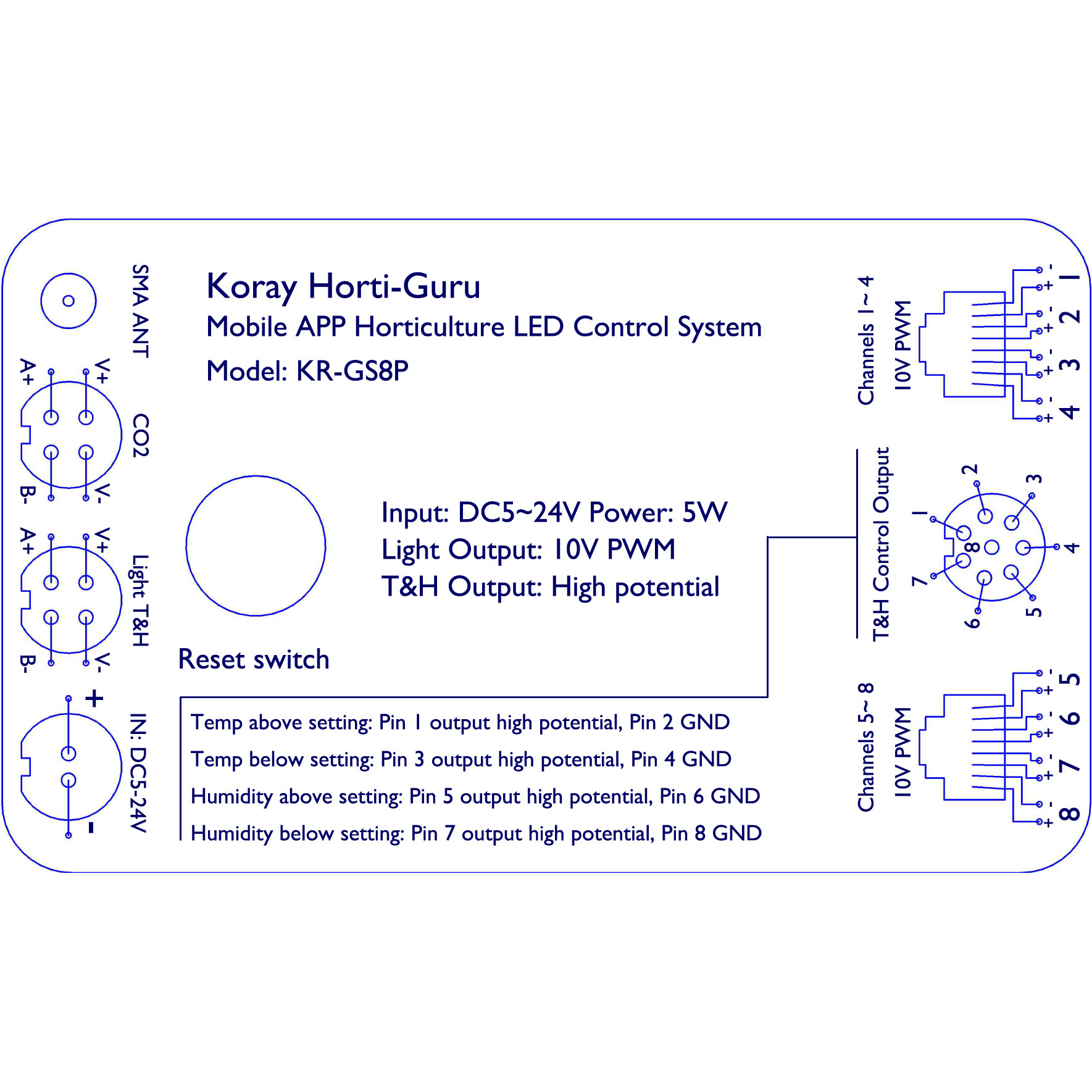
Official KR-GS8P interface and wiring diagram (media 6070): SMA antenna, CO₂ port, Light T&H port, input DC5~24 V, Reset switch, channels 1–4 / 5–8 10 V PWM terminals, and the Pin1–Pin8 temperature/humidity control output.
Because the protocol is Modbus rather than a proprietary pair, the practical consequence is substitution: a failed probe can be replaced with another register-compatible Modbus device instead of a factory-matched spare. The engineering consequence is that sensor address and baud configuration must be set once at commissioning, and that the bus should be run as a daisy chain rather than a star.
8-Channel 10 V PWM Output over RJ45 Sockets
10 V PWM is a control signal whose amplitude is 10 V and whose duty cycle carries the command, so a 50 % duty cycle means “half output” and the receiving driver reads a percentage rather than a voltage level. Pulse-width signalling is used in lighting control because a duty-cycle command is far less sensitive to cable voltage drop than an analogue voltage level of the same nominal range.
The KR-GS8P exposes up to 8 lighting control channels in that format, and the output is presented in the app as a percentage display, which removes an analogue-voltage conversion step for the operator.
| Output group | Terminal presentation | Signal format | Maximum channels |
|---|---|---|---|
| Channels 1–4 | Dedicated 10 V PWM terminal group, + / − marked per channel |
10 V PWM, percentage display | 4 |
| Channels 5–8 | Dedicated 10 V PWM terminal group, + / − marked per channel |
10 V PWM, percentage display | 4 |
| Physical connector | RJ45 network-cable socket | — | 8 total |
Two details are worth separating from fixture-side dimming literature. First, this is an upstream, controller-side output stage; the mapping from a controller channel to a lamp’s own input interface is an installation decision, not a specification of this device. Second, RJ45 is used here as a socket type — the same eight-position connector found on network cabling — which is convenient because detachable, field-terminated cabling is available everywhere, but it does not imply an Ethernet data link on those pins.
The eight channels are also the practical reason a controller of this class exists: a room that runs separate propagation, vegetative and flowering zones, each with its own spectrum and photoperiod, exhausts a single-channel timer very quickly.
Pin1–Pin8 High-Potential Alarm Contacts
Environmental excursions are handled by a separate output block. The specification describes these as high-potential (dry-contact style) control outputs, wired as four fault conditions on eight pins, so an external alarm, interlock or building management input can be triggered without sharing a power supply with the controller.
| Condition | Pin definition | Contact reference |
|---|---|---|
| Temperature above setpoint | Pin 1 high potential / Pin 2 GND | Temp above |
| Temperature below setpoint | Pin 3 high potential / Pin 4 GND | Temp below |
| Humidity above setpoint | Pin 5 high potential / Pin 6 GND | Humidity above |
| Humidity below setpoint | Pin 7 high potential / Pin 8 GND | Humidity below |
Keeping the two directions separate — above and below, for both temperature and humidity — matters in horticulture because the corrective actions are opposite. An over-temperature event calls for more airflow, while an under-temperature event calls for heat; a single “climate fault” contact cannot distinguish them, and a controller that does can hand the decision to the equipment that is actually able to act.
One-Year Light Recipe Scheduling Across Growth Stages
The longest schedule interval is up to one year, and the schedule is editable per stage: spectrum and intensity can be set separately for germination, group cultivation, vegetative growth, flowering, fruiting and harvest. A built-in growth program for medicinal plants ships with the unit, and custom recipes can be written over it.
The engineering point is that a one-year horizon is not the same thing as a long timer. A single setpoint held for twelve months is a timer; a twelve-month horizon in which the spectrum and intensity change at each stage boundary is a recipe, and it is the boundary conditions — not the endpoints — that decide whether a crop finishes on plan. The scientific basis for stage-specific light quality is the regulation of plant secondary metabolism by the light environment, which is an active research area summarised in the peer-reviewed literature [2][3].
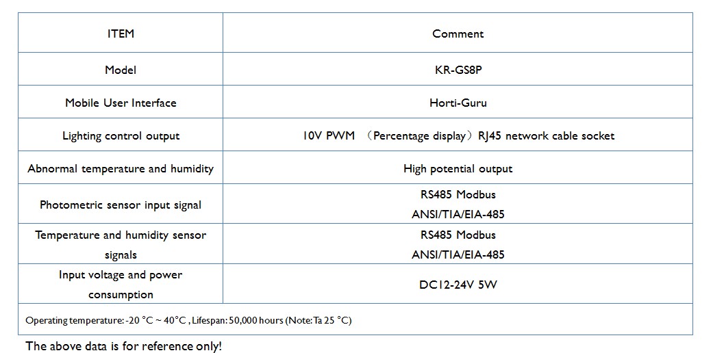
Official KR-GS8P specification table (media 6868). Note that the specification table lists input DC12-24 V / 5 W, while the interface diagram in the previous section labels the same input DC5~24 V / Power 5 W; both are the manufacturer’s published figures and are reproduced here side by side rather than merged.
KR-GS8P Specification Summary
| Parameter | Value | Notes |
|---|---|---|
| Model | KR-GS8P | Mobile app horticulture LED control system |
| Mobile interface | Horti-Guru (mobile app) | Percentage-based light display |
| Lighting control output | 10 V PWM, up to 8 channels | RJ45 network-cable socket |
| Channel breakout | Channels 1–4 and 5–8 terminal groups, + / − per channel |
Controller side |
| Environmental fault output | High-potential contacts, Pin1–Pin8 | Temp above / below, humidity above / below |
| Light sensor input | RS485 Modbus / ANSI-TIA-EIA-485 | Dedicated sensor input |
| Temperature & humidity sensor input | RS485 Modbus / ANSI-TIA-EIA-485 | Light T&H port, A+ / B− / V+ / V− |
| CO₂ input port | A+ / B− / V+ / V− |
Separate from the T&H port |
| Other ports | SMA antenna socket, Reset switch | On the interface panel |
| Schedule horizon | Up to 1 year | Spectrum and intensity editable per stage |
| Stage coverage | Germination, group cultivation, growth, flowering, fruiting, harvest | Built-in medicinal-plant program plus custom recipes |
| Input voltage / power | DC12-24 V, 5 W (spec table); DC5~24 V, 5 W (interface diagram) | Both official figures published |
| Operating temperature | −20 to 40 °C | Manufacturer data |
| Lifespan | 50,000 hours (Note: Ta 25 °C) | Manufacturer data |
| Certifications | CE / RoHS / FCC | Product page listing |
| Dimensions and weight | Not published on the official product page | — |
| Optical ratings (PPF / PPFD / efficacy) | Not applicable — this is a controller | No lamp optics are claimed |
Official sources for the figures above: the KR-GS8P product page (product ID 8700), the official specification table (media 6868), the official interface diagram (media 6070) and the official product PDF (media 6866) [4][5].
Where a Bus Controller Fits — Application Guidance
The official use case for this class of device is commercial planting of medicinal plants and professional experimental planting. Those two settings share a specific trait: the cultivation plan is written down before the crop starts and then must be executed identically across cycles. A bus controller earns its place when several zones, several lamp groups and at least one climate probe have to stay on one timeline — the 8 PWM channels carry the zoning, the RS485 pair carries the measurement, and the Pin1–Pin8 contacts carry the escalation.
It is the wrong purchase in two cases. In a single-zone, single-spectrum room with a fixed photoperiod, an ordinary timer delivers the same result for less wiring. And in any facility where the fixture’s own dimming interface has already been specified by the luminaire supplier, adding a second control authority usually creates a conflict rather than redundancy.
Where a bus architecture is the right fit, Koray Opto-Electronic builds on 17 years of experience and 300+ domestic and international patents across its horticultural lighting and control range [4].
FAQ
Is KR-GS8P a lamp or a controller?
It is a controller. The official specification defines lighting control outputs, sensor inputs, alarm contacts, a power budget of 5 W and an operating temperature range — it publishes no PPF, PPFD or luminous flux figure, and none can be inferred for it.
How many lighting channels does it control, and in what signal format?
Up to 8 channels of 10 V PWM, presented as a percentage in the Horti-Guru app, delivered on an RJ45 network-cable socket with the channels split across 1–4 and 5–8 terminal groups.
Which sensors can it read?
Two RS485 Modbus (ANSI/TIA/EIA-485) inputs — one for a light sensor and one for temperature and humidity — plus a separate CO₂ input port. Each uses the A+ / B− / V+ / V− terminal pattern.
How long can a light recipe run?
Up to one year, with spectrum and intensity editable independently for germination, group cultivation, growth, flowering, fruiting and harvest stages.
Why do two official documents give different input voltages?
Both figures are published by the manufacturer: the specification table states DC12-24 V / 5 W, and the interface diagram states DC5~24 V / 5 W. They are reproduced side by side rather than reconciled, and a system designer should treat the intersection of the two as the safe operating window.
References
- Michigan State University Extension — Light Management in Controlled Environments: https://www.canr.msu.edu/floriculture/resources/light-management
- Frontiers in Plant Science — review of light-regulated plant secondary metabolism: https://www.frontiersin.org/journals/plant-science/articles/10.3389/fpls.2025.1644472/full
- PubMed Central — review of light regulation of secondary metabolite synthesis and accumulation: https://pmc.ncbi.nlm.nih.gov/articles/PMC12358498/
- Official KR-GS8P product page (product ID 8700): https://koraylights.com/product/gs8p-mobile-app-gardening-led-intelligent-control-system-plant-light-1/
- Official KR-GS8P product PDF (media 6866): https://koraylights.com/wp-content/uploads/2020/02/GS8P-mobile-APP-Horticulture-LED-control-system-plant-light-temperature-and-humidity-controller.pdf
- USDA Agricultural Research Service (institutional reference for controlled-environment research): https://www.ars.usda.gov/




Leave A Comment