
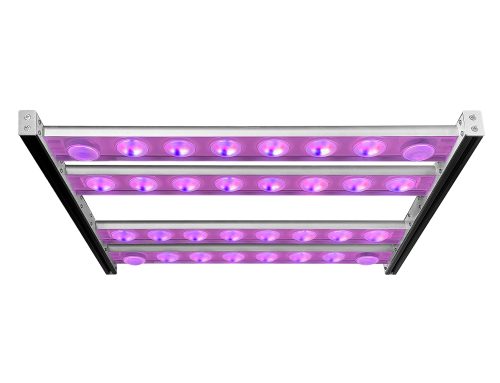
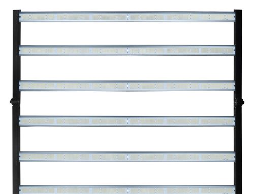
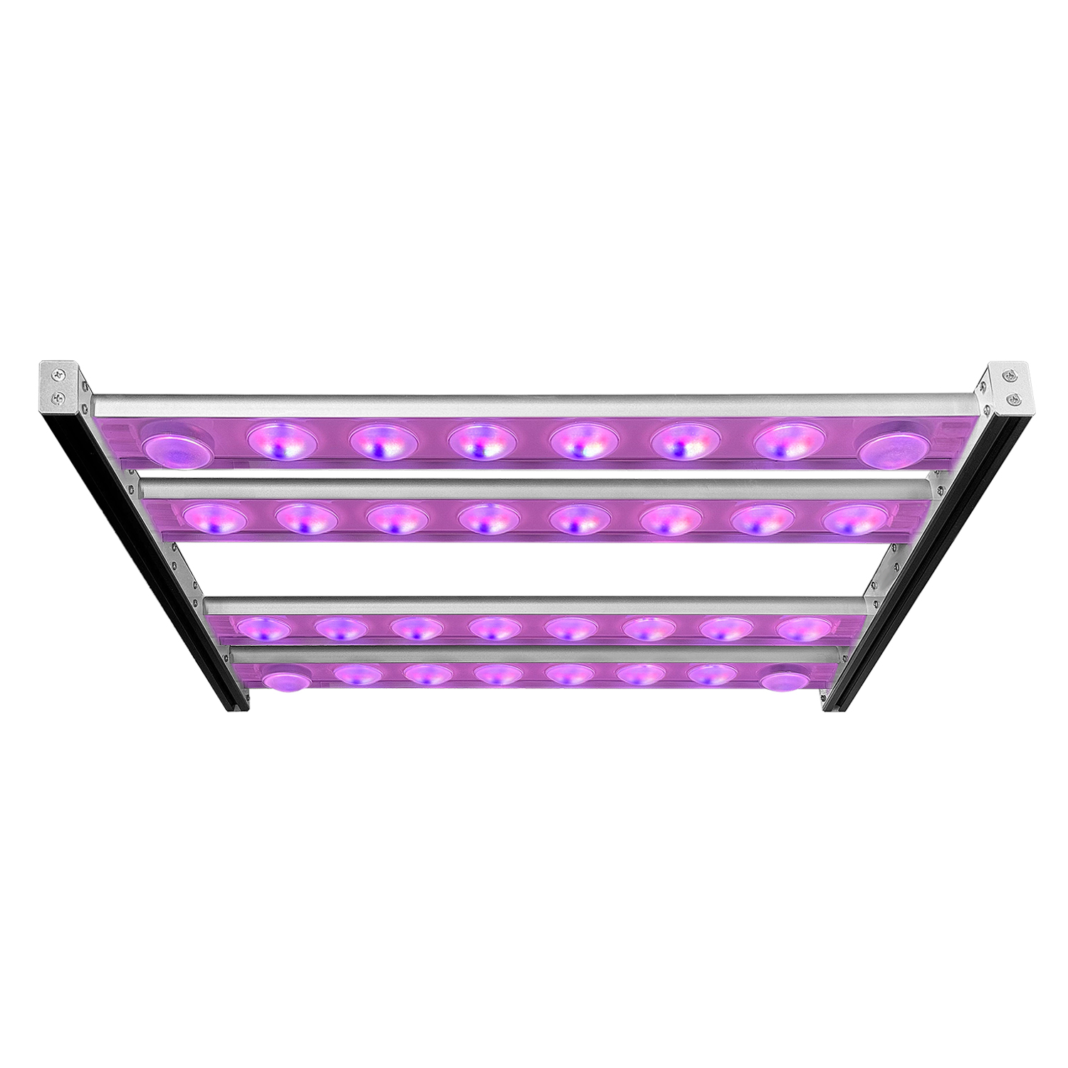
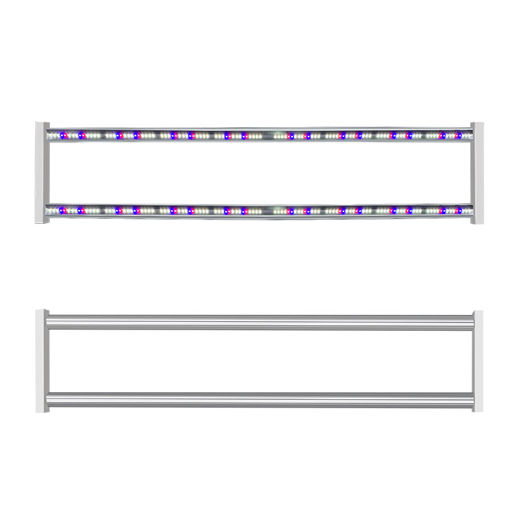
A quantum board grow light is a flat, high-density LED panel that distributes many emitters across a broad substrate instead of concentrating a few high-power diodes behind a small optic. The RX-LM301-312-K2 is listed on its official product page (https://koraylights.com/product/qb-board-grow-light-rx-lm301-312-k2/) as a QB Board Grow Light built around “Samsung LM301 chips”, with photon efficiency “up to 2.8 µmol/J” that the same page raises to “up to 3.2 µmol/J” once “added 660 nm deep red” is included. Its board measures 24.8 in × 7.9 in × 2.7 in, or 630 × 200 × 68 mm, it accepts AC100–277 V, and its maximum power is 240 W. The sections below read those published figures as board-level electrical calibers — the efficiency, voltage, power and size numbers that decide whether a board belongs in a given installation — and separate the values that can be used in a plan today from the ones that still have to be requested.
What a quantum board is in a horticulture installation
A quantum board is a luminaire whose emitters are spread across a broad, flat substrate rather than packed into a single point optic. Photosynthetically active radiation is the 400–700 nm waveband that the photosynthetic apparatus absorbs, and a horticultural luminaire’s output inside that band is counted as photon flux in micromoles per second. Because two luminaires of equal nominal wattage can deliver very different amounts of that photon flux, the industry compares them on delivered light and on efficacy rather than on lamp wattage alone; the DesignLights Consortium maintains its horticultural lighting program (https://www.designlights.org/horticultural-lighting/) for exactly that purpose, publishing criteria that separate a rated electrical input from the photons a fixture actually emits.
A board format changes the selection problem. In a small, high-power fixture the designer trades beam angle against mounting height in a compact volume; on a wide board the emitters are already spread out, so the board’s dimensions and its photon output per unit area carry more of the design load than the optic does. The United States Department of Agriculture’s Agricultural Research Service (https://www.ars.usda.gov/) conducts and publishes plant-lighting research on how photon flux, spectrum and duration interact with crop response — a reminder that a board’s headline efficiency is one input into a lighting plan, not a substitute for one.
How photon efficacy is counted, and why µmol/J is an electrical caliber
Photon efficacy is the ratio of emitted photosynthetically active photon flux to electrical power drawn, expressed as micromoles of photons per joule of energy. Its reciprocal, joules per micromole, is an energy cost per unit of light, so µmol/J is simultaneously a performance figure and an electrical caliber: it states how many photons a board returns for each joule that the circuit must supply. A value of 2.8 µmol/J means that each joule delivered to the board produces 2.8 micromoles of PAR photons in the measurement conditions behind the rating.
Two cautions follow directly from the definition. First, a µmol/J figure is attached to a stated operating point; it is not a constant that holds at every drive current, temperature and spectrum. Second, because the denominator is electrical power at the board, the number is only meaningful alongside the input voltage and the maximum power the board is specified to accept. Both of those are published for this board, and both are needed before the efficacy figure can be mapped onto a circuit.
The 2.8 µmol/J baseline and the 3.2 µmol/J figure with added 660 nm deep red
The official page publishes two efficiency figures for this board rather than one. It states photon efficiency “up to 2.8 µmol/J” for the board as built on Samsung LM301 chips, and it states light efficiency “up to 3.2 µmol/J” once “added 660 nm deep red” is included. The two numbers describe the same board platform under two configurations, and the word “up to” marks each as a best-case value within the rated conditions rather than a guaranteed operating figure.
For specification work the practical reading is that the board’s efficiency is configuration-dependent. A plan built on the 2.8 µmol/J figure describes the LM301 baseline; a plan built on 3.2 µmol/J describes the version with the added deep-red channel. Because the page ties 3.2 µmol/J to the added 660 nm content, the higher figure should be quoted together with its spectrum condition, not on its own. Where a plan needs the efficiency at a specific drive current or case temperature, that point is not separately published and falls into the items to confirm in writing.
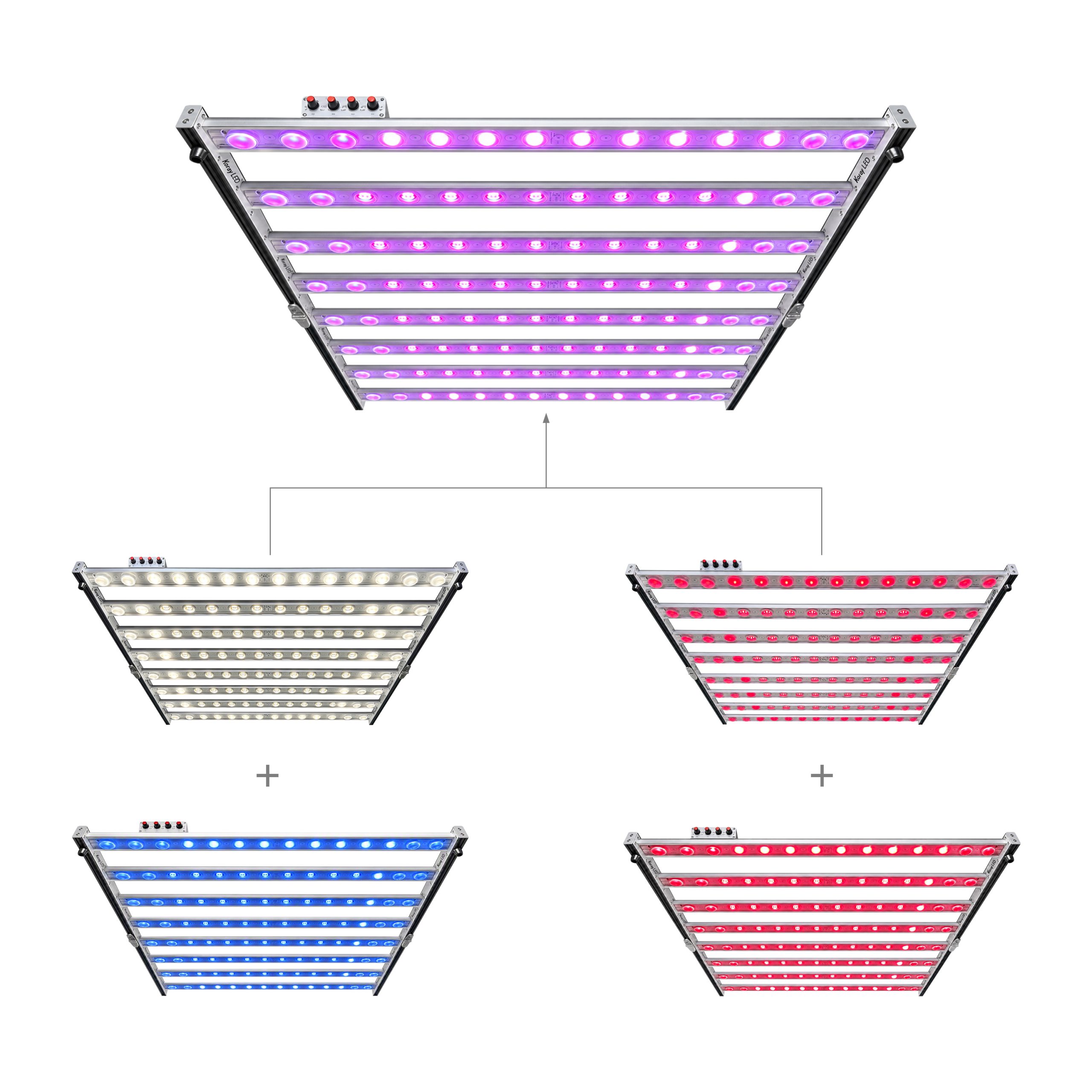
What the 660 nm deep red channel changes
Deep red around 660 nm sits inside the chlorophyll absorption region within the 400–700 nm PAR band that the definition above covers, which is why added deep-red content is usually described in terms of spectrum rather than raw output. The addition does not change the fact that PAR is what is being counted; it changes the distribution of that PAR across the band and, for this board, it is the configuration the page associates with the higher 3.2 µmol/J figure.
The design consequence is a spectral one. Adding a channel introduces a second spectral component to plan around and to verify, so the emitter mix and the resulting spectrum belong in the specification next to the efficacy figure. The page states the emitter as Samsung LM301 chips and describes the deep-red addition, but it does not publish the precise mixing ratio or a spectral distribution chart; those are not specified in the official datasheet and should be requested when a plan depends on a particular spectrum.
The 630 × 200 × 68 mm board and the 240 W engine
The board is published at 24.8 in × 7.9 in × 2.7 in, which converts to 630 × 200 × 68 mm, and its maximum power is 240 W. Read together, those figures give the board’s power density: 240 W spread across a 630 × 200 mm face, with the 68 mm covering the depth that includes the emitters and the mounting standing behind them. That depth matters in a low-clearance installation, because it sets how much vertical space the board itself occupies before any gap to the canopy is added.
The board is also described as customizable in size, power, spectrum, PAR output and PPFD output. That is an important qualifier: the published 240 W and the published dimensions describe the standard configuration, and the customization list confirms that the platform can be resized and re-rated. A plan that depends on a non-standard board should therefore treat the published numbers as the baseline rather than as the final electrical input, and should request the customized drawing.
AC100–277 V input and what a wide input range implies
The published input voltage is AC100–277 V. A range this wide spans both nominal mains classes used in commercial buildings: the 120 V class common in North America and the 230–240 V class common elsewhere, plus the 277 V leg that appears in some commercial lighting circuits. One board can therefore be specified against several supply systems without a change to the luminaire itself, which reduces the number of electrical variants a project has to carry.
The range is an input tolerance, not a statement about drive current or dimming. The same page’s customization list covers power and PAR output but does not publish a driver model, a dimming protocol or a power-factor figure; those are not specified in the official datasheet. When a project needs the board on a controlled or metered circuit, the driver and the control interface should be confirmed from the supplier before the electrical design is frozen.
50,000 hours, certifications and what a lifespan figure covers
Service life is published as 50,000 hours. A lifespan figure of that kind is a projected operating duration under defined conditions — commonly stated at a reference case temperature and drive current — so it should be read together with its test conditions rather than as a calendar guarantee. The page publishes the hours but not the full test conditions; the reference current and temperature behind the 50,000-hour figure therefore fall under the items that are not specified in the official datasheet and are worth requesting with the data.
The board is listed with CE, RoHS and FCC certification. Those marks address conformity, hazardous-substance restriction and electromagnetic compatibility respectively; they are compliance facts about the product, and they are quoted here exactly as the page publishes them. They do not by themselves state a photometric test standard, and no photometric standard is named on the page.
Board-level calibers side by side
| Dimension | LM301 baseline | With added 660 nm deep red |
|---|---|---|
| Emitter | Samsung LM301 chips | Samsung LM301 chips plus added 660 nm deep red |
| Photon efficacy | up to 2.8 µmol/J | up to 3.2 µmol/J |
| Board size | 24.8 × 7.9 × 2.7 in (630 × 200 × 68 mm) | same board |
| Input voltage | AC100–277 V | same board |
| Maximum power | 240 W | same board |
| Service life | 50,000 hours | 50,000 hours |
| Customization | size, power, spectrum, PAR output, PPFD output | same list |
| Certifications | CE, RoHS, FCC | CE, RoHS, FCC |
| Exact PPFD map | not specified in the official datasheet | not specified in the official datasheet |
| Thermal derating | not specified in the official datasheet | not specified in the official datasheet |
| Driver model | not specified in the official datasheet | not specified in the official datasheet |
| IP rating | not specified in the official datasheet | not specified in the official datasheet |
The table places the two published configurations on the same rows so that the only differences — the emitter mix and the efficiency figure — stand out from the platform-level values that are shared, and so that the unpublished items are visible rather than implied.
Fit-for-purpose scenarios
With the calibers above settled, the board’s fit is a question of which configuration matches the target spectrum and which supply the site already runs. A project that wants the LM301 baseline as its operating point should specify against the 2.8 µmol/J configuration, while a project whose spectrum target includes added deep red should specify against the 3.2 µmol/J version and record the spectrum alongside it. The wide AC100–277 V input suits sites that carry more than one mains class, and the 630 × 200 mm face suits arrays built from several boards rather than a single large fixture. Koray, with a 17-year record in horticultural lighting, builds this board on the readable, published figures above; where the plan depends on a value the page does not print — the PPFD distribution, the thermal derating curve, the driver, the ingress protection — the sensible move is to request it before the design is frozen rather than to assume a value.
What to confirm in writing before specifying
The following items are not specified in the official datasheet and should be requested from the supplier alongside the standard figures: the exact PPFD map at the intended mounting height, the thermal derating curve, the driver model and its dimming interface, the IP rating, the spectral distribution behind the added 660 nm content, the emitter mixing ratio, and the test conditions behind the 50,000-hour service-life figure. Requesting them together keeps the electrical design, the photometric plan and the compliance record consistent from the start.
Frequently asked questions
What do the 2.8 µmol/J and 3.2 µmol/J figures mean?
They are two published photon-efficiency values for the same board platform. The page states photon efficiency up to 2.8 µmol/J on Samsung LM301 chips, and light efficiency up to 3.2 µmol/J once added 660 nm deep red is included. Each is marked “up to”, so each is a best-case value within the rated conditions, and the higher figure is tied to the deep-red configuration.
What are the board’s physical and electrical calibers?
The board is published at 24.8 in × 7.9 in × 2.7 in, or 630 × 200 × 68 mm, with maximum power 240 W and an input range of AC100–277 V. Service life is 50,000 hours and the page lists CE, RoHS and FCC certification. The board is also described as customizable in size, power, spectrum, PAR output and PPFD output, so these are baseline values for the standard configuration.
What does adding 660 nm deep red change?
Deep red around 660 nm lies within the 400–700 nm PAR band, so the addition changes the spectral distribution of the emitted light rather than the definition of the output. For this board it is the configuration the page associates with the higher 3.2 µmol/J figure. The precise mixing ratio and a spectral distribution chart are not specified in the official datasheet.
Is an IP rating or driver model published?
No. The IP rating and the driver model are not specified in the official datasheet, and neither is a dimming interface or a power-factor figure. If the project needs the board in a wet or controlled circuit, those details should be requested from the supplier before the electrical design is finalized.
What should be confirmed in writing before ordering?
Request the exact PPFD map at the intended mounting height, the thermal derating curve, the driver model and dimming interface, the IP rating, the spectral distribution behind the added deep red, the emitter mixing ratio, and the test conditions behind the 50,000-hour lifespan. These are the values the page does not publish, and they should be recorded before the specification is frozen.


Leave A Comment